For the majority of us, the age-old curse of the work day has been that usually, our day starts with the jarring, annoying buzz of an alarm clock.
For me, the only thing that makes this situation worse is when you happen to wake up before the alarm only to find out that you only have less than an hour before that blasted thing goes off - and of course you can't really doze off again knowing that the alarm will soon go off.
One purpose of this project was to have a bit of a clever way to play a trick on my mind during those early morning hours. Usually, when you first wake up, your brain is not yet fully functional. With the clock being in "reverse", you really need to have your wits about you in order to figure what time it really is - of course, the alarm will help you get fully alert!
When it's not busy waking you up, it will cause people to do a bit of a double take whenever they need to find out what time it is.
This project takes advantage of a very simple alteration that you can make to almost any quartz clock movement to create a very unique time piece.
Step 1: Gathering Your Parts
The basis for the project was a very cheap alarm clock that I got from my local dollar store.
While I could have simply modified this clock movement to go backward and just left it at that, I did want to create to a project that was something a little more unique by housing it in a more fancier case.
As a companion guide of this Project, I've also created a series of videos that step through the construction of this clock. These videos can be found clicking this link
To make the clock you need to gather the following items:
Materials
- One Cheap Alarm Clock - I paid about 3 dollars for mine at my local dollar store
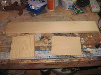
- 8-inch piece of 1 x 6 pine - for the clock base
- 2 feet of 1 x 4 pine - for the clock case
- 4.5 inch X 5 Inch piece of 1/8 inch plywood - for the clock face
- 4.5 inch X 5-inch piece of 1/8 inch plexiglass - for the clock face
- Wood Stain - any color that you want
- Spar Varnish - any clear varnish is fine - but I like the look that Spar Varnish gives
- White Paint - for the clock face
- Black Paint - for the edge of the clock base and the back of the clock
- 1 inch "Peel and Stick" Numbers - for the clock face
- 4 1-1/4 inch wood screws
- 2 Sided Tape - optional
- Felt Pads - for the bottom of the clock
- 1 AA battery - Your clock won't work without power!
- Wood Glue
Tools
- Table Saw
- Miter Saw
- Router with a Corner Round Router Bit and a Roman Ogee Router Bit
- Screw Driver
- Plexiglass Cutting Tool
- Drill or Drill Press with a 1/4 inch drill bit
- Paint Brush
- Miter Square
- Clamps
Step 2: Making the Clock Run Backwards
While in this particular case I will be making this modification to an alarm clock module, this sort of alteration can be done to almost any quartz clock movement.
To start, let's get rid of that cheap plastic case in order to get at the clock movement. For the most part, this should be a fairly simple matter of removing any screws that are holding the case together until you are able to access the clock movement and the hands of the clock.
Once you have the clock hands and movement exposed, remove the clock hands, including the hour and minute hands, second hand and the alarm time hand by gently pulling them off the spindle of the clock movement. Set the clock hands aside to be used later.
Next, remove the clock movement from the clock face. Typically there are a couple of ways that clock movements are attached to the clock faces. On way is that the clock is attached to the face with a small nut on the clock movement spindle, while another is that the clock movement is attached to the clock face from the back with screws. In the case of my alarm clock, the clock movement was attached to the clock face with 2 screws. With the removal of the screws, the clock movement was now free.
In order to get at the internals of the clock movement, we need to open the case of the movement.
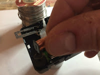
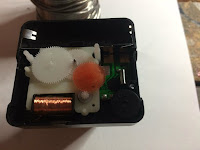
First, start by removing the knobs that set the time and alarm time by gently pulling them out of the back of the clock movement. Once removed the next step is to open the movement case. The movement will be contained in a plastic case that is usually held together with locking tabs on all four sides of the case. Using a screwdriver, you can gently lift the tabs on the case until you can separate the 2 halves of the case. (A word to the wise: - make sure that the spindle end of the movement is pointing down before you do this, otherwise you may find a bunch of gears scattered all over your workbench!) Once you've opened the case, you should see a series of gears and an electromagnet.
It's the electromagnet that we need to alter in order to make the clock run backward. More specifically, we need to reverse the polarity of the electromagnet so that the north and south poles of the magnet are reversed. In the case of our clock, the electromagnet comprises of an electromagnetic coil and a magnet element.
To fully get at the electromagnet, carefully remove the gear assembly from the clock (and place it in an out of the way place). With the electromagnet now fully exposed, carefully remove the magnet element and coil from the clock - making sure that you do not damage the wiring on the coil.
Remove the magnet element from the coil by sliding it out of the coil and flip the magnet element on its horizontal axis. (To see this "flip" in more detail, please view the linked video enclosed in this step). Reinstall the magnet element back into the coil.
Reinstall the electromagnet back into the clock, followed by the gear assembly that you previously removed. Make sure that the gears are fully seated into the clock.
The last step is to reattach the back cover of the clock movement, however, before reattaching the back cover, take a moment to make sure that the alarm on-off switch is moving freely and working properly. The cover is then reattached by pressing down until the plastic tabs click into place.
Replace the time and alarm set knobs
At this point, give the clock a quick test run. Take the second hand and reattach it to the shaft of the clock module, and install a battery into the clock. If the second start moving "backward" - Congratulations! You now have a Backwards Clock!
Step 3: Cutting Out the Clock Face
To make the clock face, take the 1/8 inch piece of plywood and draw a diagonal line from each corner of the plywood to the opposite corner for each corner. When complete, the diagonal lines should meet in the middle of the plywood clock face at an "X". This "X' will mark the spot that we will be drilling the hole for the spindle on the clock movement later on.
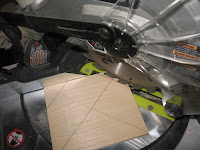
Next, at the top of the plywood, measure in 1.5 inches from each side of the plywood and mark the locations with a pencil. Using a 45-degree square, draw a 45-degree line from the points that you marked at the top of the plywood to the side of the plywood for both sides. When complete you should have 2 small triangles marked out at the top of the plywood at the sides.
Using a miter saw, cut off the small triangles along the lines that you marked on the plywood. When complete your plywood should now have 6 sides that are almost in the shape of a house.
Step 4: Cutting Out the Clock Case Parts
Now that the clock face has been cut out, we now focus on making the parts for the clock case.
The attached cutting diagram will serve as a guide for cutting out the case pieces. You can also look at the attached video snippet for additional guidance.
The first thing that needs to be done is to add the slots to the case parts that will act as the guides for the clock face and the Plexiglas cover for the clock face.
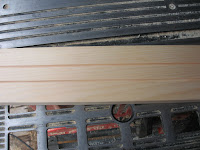
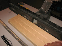
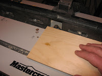
To add the slots, take the 2-foot piece of 1x4 pine and with a table saw, rip two 1/8 inch deep slots onto one side of the board. The slots need to be 1 1/4 inch in from each side of the board.
Once the slots have been added, round the lengthwise edges of the 1x4 board with the router and a corner round bit.
Now that the board is now prepared, it's time to cut. Start by cutting the two 3 1/8 inch bottom sides of the case with a miter saw. When cutting the pieces, make sure that the one end is cut at a 22.5-degree angle, with the side of the board that has the 2 slots cut into it being the inside facing part of the board (or, the side that has the "shorter" side of the angle).
Once the 2 sides have been cut, cut the two 2 5/8 inch top corner pieces. When cutting these pieces make sure that both ends are cut at a 22.5-degree angle, again making sure that the side that has the 2 slots are facing inward.
Finally cut out the 2 3/8 inch top piece. Again when cutting this piece make sure that both ends are cut at 22.5-degree angles, making sure that the side that has the 2 slots are facing inward.
With that, the basic structure of the clock case is now ready for assembly.
Step 5: Assembling the Clock Case
Now that we have all the pieces cut out, it's the time to assemble the clock case.
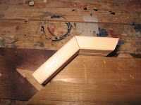
Due to the odd angles that the clock case will have, I found that using a jig made assembly easier, In this case, the jig was simply a piece of 2X4 with a 45-degree angle cut into it. Create the jig by doing a test fit with one of the bottoms and top side pieces on the 45-degree angle of the 2X4 so that the joint between the bottom and top side pieces are as tight as possible. With those 2 pieces in position on the jig, mark the spot on the 2X4 where the end of the bottom piece of the clock case sits on the 2X4.
Remove the two clock case pieces from the jig and nail in a finishing nail into the spot that you marked on the jig. This nail will be used as an anchor point when we go to glue our clock case parts together.
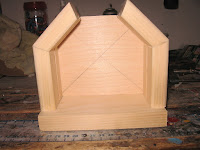
Now that the jig is all set up, we can start assembling the clock case. Start by gluing together a bottom side and the top corner side at 22.5-degree edges of both pieces. Join the 2 pieces together at the 22.5-degree edges. Put the two sides together on the jig and clamp them to the jig. Once the glue has dried, removed the assembled clock side and do the same to the other bottom and top corner side of the case.
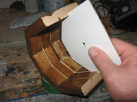
Now that the 2 sides of the clock case are glued together, use the clock face that we cut out in the previous step as a template and attach the 2 clock case sides to the clock face by inserting the clock face into one of the slots in the case sides (but don't glue them together just yet). Secure the case sides to the clock face with a clamp.
Attach the top of the clock case to the sides with some glue and set the case top into place with the clock face used as a guide. Make sure that the top of the clock case forms a tight joint with the 2 clock case sides.
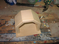
Once the glue has dried, remove the clamps and remove the clock face by sliding it out of its groove in the clock case.
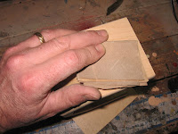
Give the case a good sanding, and then stain and varnish the clock case to the color of your choice
Step 6: Preparing the Clock Face
With the clock case now assembled, we now focus our attention back to the clock face. In a previous step, we had marked the center of the clock face with 2 diagonal lines that met in the middle of the clock face at an "X". Using a 1/4 inch drill bit and a drill press, drill a hole right in the middle of the "X" on the clock face. This hole will serve as the location for the spindle of the clock movement. At this point, it would be a good idea to give the clock movement a test fit to ensure that the hole is large enough for the spindle to fit through and adjust as necessary.
Next cut out the Plexiglas face for the clock, Using the plywood clock face as a template, trace out the outline for the plywood clock face on a sheet of 1/8 inch Plexiglas. Once the shape is traced out, cut the shape out of the Plexiglas with a Plexiglas cutter.
Finally, give one side of the plywood clock face a couple of coats of white paint.
Step 7: Adding the Clock Face to the Case
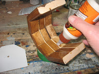
Next on the list is to permanently attach the clock face to the clock cabinet. To do that, we first need to apply a little bit of wood glue to the rear inside groove of the case. (Remember - You only need to add a little bit glue along that groove).
With the glue applied, slide the clock face into the rear groove of the clock face. Make sure that the painted white side of the clock face is facing towards the other inside groove of the clock face. Make sure that the clock face is firmly seated into the groove and wipe away any excess glue.
Once the glue has dried, give the unpainted side of the clock face a coat of black paint,. If desired you can also paint the neighboring edges of the clock case black too.
Once the paint is dry we are now ready to attach the clock movement.
Step 8: Attaching the Movement and Dial
To attach the clock movement to the clock face, first, apply a little bit of glue to the front of the clock movement. Make sure that you don't get any glue near any holes in the clock movement that might allow the glue to get into the clock movement itself.
Once the glue is applied, mount the clock movement onto the back of the clock face (the side that you painted black earlier). Make sure that the clock movement is seated squarely into the face and that the spindle of the movement is protruding out the front of the clock face.
Once the glue is dry, reattach the alarm, minute, hour and second hands onto the clock movement spindle. Adjust the hands so that the clock is in the 6 o'clock position.
Using the peel and stick numbers, start laying out the dial on the clock face by putting the number 6 where the hour hand is pointing. Once you have the number 6 place on the clock face, move the clock hands by using the time adjustment knob on the back of the clock movement until the clock is in the 5 o'clock position (remember - this is a backward clock - so in this case, 5 o'clock is actually 7 o'clock on a "normal" clock). Take the number 5 from your peel and stick sheet and again place it on the clock face where the hour hand is pointing.
Keep repeating this process until all the hours are indicated on the clock face,. As you are applying the numbers, take care to apply the numbers so the clock face is as symmetrical as possible.
Once the dial numbers have been applied, the final step is to calibrate the time for the alarm to go off. To do this, once again set the clock to 6 o'clock using the time adjustment knob in the back of the movement. With a battery inserted into the movement, turn the alarm on and move alarm set knob on the back of the clock movement until you hear the alarm go off. Once the alarm goes off, manually move the alarm set hand on the clock face by manually moving the hand (not using the alarm set knob) to the 6 o'clock position on the clock face.
Step 9: Making the Base
With the completion of the clock case and face, we now focus our attention on the base of our clock.
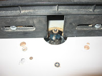
Taking the 8-inch piece of 1X6 pine board and using the router with a Roman Ogee bit installed, add a decorative edge along the 4 sides of the pine board.
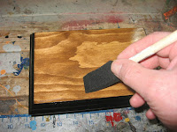
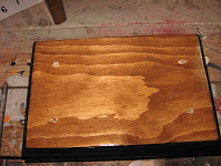
Once the edges have been applied by the router, give the base a general sanding until all the surfaces are smooth. Stain the base the same color that you gave the clock case.
Once the stain has dried, give the clock base a bit of pizzazz by painting the routed edges of the base with black paint.
Once the paint has dried, give the base a coat of varnish.
Step 10: Adding the Clock Case to the Base
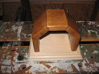
Finally, it's now time to put everything together. First, turn the base upside down and place the clock case in the center of the base. To make sure the case is truly centered on the base, make sure that the clock case is 7/8 of an inch in from each side of the base.
Once the case is centered, mark out the outline of the case onto the back of the base with a pencil.
Remove the clock case from the base. Within the outline that you have now drawn on the base, make a mark 1 inch in from each edge of the marked outlines - you should have 4 marks made into the base
Using the drill press, drill a 1/4 inch at each of the 4 points that you have marked on the base. Once the holes have been drilled, Turn the base over so that the stained and varnished side is facing up.
Take the 1/8 inch piece of plexiglass that was cut out in a previous step and slide it into the remaining inside groove of the clock case until it is seated firmly within the case.
In order to attach the clock case to the base, we will need to attached screws from the bottom of the base. To make that easier, we would need to flip the case and base as a unit upside down in order to insert the screws. In order to help keep the case in place on the base while it's upside down (and before we can get the screws installed) using some double sided tape to attach the clock case to the base would be helpful.
Once the tape is installed, attach the case to the base, making sure the case is again centered on the base. Once the case is centered, firmly press the clock case into the base so that the double sided tape joins the case and base together.
Flip the now assembled clock upside down and screw the four 1 1/4 inch wood screws into the base via the 4 holes that were drilled into the base.
Step 11: The Finishing Touches
To finish off the clock, apply some felt feet to the bottom of the clock, flip the clock right side up, and install a battery - The clock is now almost ready for wake up duty!
Set the clock to the correct time as you normally with the time set knob in the back of the clock and set the alarm to the time you want with the alarm set knob.
I've been using this clock to wake me up for a number of months now. It certainly has made for an interesting conversation piece, while doing a very good job getting me up in the mornings.






























No comments:
Post a Comment