The last time I talked about the IOT weather station, I had just finished putting together a workable way to power the station with solar power.
Now that I have the electronic solution worked out, the final step was to house everything in a weather resistant enclosure that still allowed the station access to the outside air in order to ensure accurate readings.
Basically what I needed to construct was a Stevenson Screen.
A Stevenson Screen, to quote Wikipedia, is:
"... A Stevenson screen or instrument shelter is a shelter or an enclosure to protect meteorological instruments against precipitation and direct heat radiation from outside sources, while still allowing air to circulate freely around them.[1] It forms part of a standard weather station. The Stevenson screen holds instruments that may include thermometers (ordinary, maximum/minimum), a hygrometer, a psychrometer, a dewcell, a barometer, and a thermograph. Stevenson screens may also be known as a cotton region shelter, an instrument shelter, a thermometer shelter, a thermoscreen or a thermometer screen. Its purpose is to provide a standardized environment in which to measure temperature, humidity, dewpoint, and atmospheric pressure...."
While I was doing research on how the Stevenson screens are built, I found out that these screens were typically simple boxes that had double louvered sides. The plan for my screen was to build it as simple as possible while maintaining the necessary protection from the elements.
Eventually, I happened across the Weather for Schools web site where I found plans for a simple weather box. After reviewing the instructions, I realized that, with some minor modifications, this would work nicely for what I wanted to do.
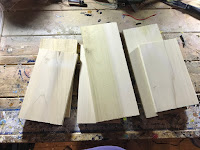
To start the build I first cut out the basic shape of the box by cutting out the pieces as I have identified in the cutting diagram below using some 1/2 inch scrap birch that I had laying around.
When I cut out the side pieces, I also cut a 15-degree angle along one end.
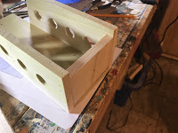
I then drilled a 1-inch hole at every spot that I marked,
These holes will act as the ventilation holes in order to allow air flow to the weather station
Next, I attached the sides of the Stevenson screen to the back piece with some brad nails and wood glue.
I then drilled a 1/8 inch hole at the top of the back piece to act as a mounting point for the completed Stevenson screen.
With the sides and back attached I then attached the bottom of the Stevenson screen to the sides and back, but first I needed to drill a small 5mm hole in the center of the bottom.
The reason for the hole is to give me some way to visually indicate when the weather station was transmitting data. As you may recall, I programmed the NodeMCU to flash an LED when it was sending data,
My plan was to install the LED into the bottom of the Stevenson screen so that I can visually tell when a transmission is occurring.
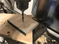
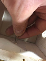
I drilled the hole in the center of the bottom by marking 2 diagonal lines between the corners of the bottom piece and drilling the hole where the 2 lines intersected in the middle.
Once the hole was drilled, the bottom was then attached to the screen with some glue and brad nails.
Finally, I attached the top of the Stevenson screen in pretty much the same manner that I did with the bottom in that I needed to first drill a hole into the center of the top to allow the wires from the solar cell to pass through.
Once the hole was drilled, the top was attached to the sides and back of the Stevenson screen with some glue and brad nails.
Now that the body of the screen was pretty much built, I then took the time to give the Stevenson screen a coat of white paint. White is recommended so that the sun's rays can be reflected off the Stevenson screen and not directly affect the interior temperature.
The next thing I focussed on was the door. I wanted to have the ability to open the door so that I can easily check on the condition of the weather station.
In order to make the door easier to open, I decided to install a small wooden drawer pull that I happen to have sitting in my junk box.
To install the door pull, I marked a spot in the center of the top of the door and drilled a 1/8 inch hole at that location.
I then installed the door pull in the drilled hole.
I then installed the door. I started first by attaching a hinge to the bottom of the Stevenson screen with some screws.
Once one half of the hinge was attached to the bottom, I then attached the other half of the hinge to the bottom edge of the door.
Once I installed the hinge, I then tested the door to make sure that I could open and close the door fairly easily.
And with that, the Stevenson screen was basically complete.
The next step in the process is to install the electronics of the weather station into the Stevenson Screen itself.
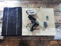
First I started by collecting all the various bits of electronic LEGO that I used in my last post when I was building the solar battery charging circuit for the weather station.
I started the install by first soldering hook up wires to the positive and negative terminals of the solar panel.
Once the solder had cooled I then applied a small dab of hot glue to the solder joints in order to provide some weather protection to the joints.
I then applied some hot glue to the top of the Stevenson screen, routed the wires attached to the solar panel through the top of the screen and attached the solar panel to the top of the screen.
With the solar panel installed, the next step was to wire up the solar charger controller board. As I mentioned in my last post about the weather station, connecting the controller board is a simple matter of wiring the positive and negative wires from the solar cell to the input terminals on the controller, soldering the battery holders to the battery terminals and finally soldering the 5 volt converter to the output terminals of the controller.
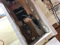
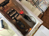
With the electronics all wired up, they are then installed into the Stevenson screen by securing them to the back of the screen with some hot glue
When I installed the components, I made sure to leave enough room at the bottom of the Stevenson Screen to allow for the installation of the NodeMCU and sensor.
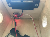
Before installing the NodeMCU, I first installed the LED into the bottom of the screen and secured it in place with some hot glue.
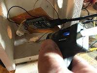
Finally, I applied some hot glue to the back of the NodeMCU and sensor module and installed it into the back of the Stevenson Screen.
Finally, I soldered the LED to the NodeMCU board, plugged the NodeMCU into the 5-volt converter and installed the lithium batteries.
With any luck at all, the weather station should power right up.
Before wrapping things up I then applied a coating of hot glue on top of all the exposed electronic surfaces to serve as weatherproofing.
And with that - the Weather Station was installed and the Stevenson Screen was ready to go.
To install the Stevenson Screen, I selected a spot that would get a fair bit of air movement while at the same time provide enough direct sunlight during the day to keep the batteries charged.
So far the weather station is working quite well and has been staying powered up continuously since I installed it about 6 months ago.
In the end, the whole station cost me about 15 dollars to build - considering what it would cost to buy a similar weather station with wireless internet connectivity from a store, it's quite the bargain.
In the end, the whole station cost me about 15 dollars to build - considering what it would cost to buy a similar weather station with wireless internet connectivity from a store, it's quite the bargain.















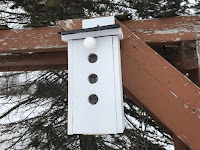
Your Stevenson screen design is all wrong. Drilling holes for ventilation won't work. You will end up with the sun shining through the holes, as well as rain and snow. You have to have louvers with a double roof and slatted floor.
ReplyDeleteGranted, not a traditional design - but I had found that the placing the sensors along the back wall of the screen prevented a lot of the environmental exposures. I also have it more of a north-south alignment - which seems to eliminate the direct sun exposure.
ReplyDeleteOddly enough after a couple of years in place, I haven't really found any snow (or rain) getting inside, even after the major blizzard that we just had. If there was, it would have really messed up the electronics.
Of course, I've gotten a 3d printer since then - It would actually be not a bad time for a bit of an upgrade :)
A Bird house.
ReplyDeletenice post
ReplyDelete