In my last post, I discussed that there seemed to be a lot of neat projects published in the "How-To" magazines that were put out over 50 years ago.
While I marveled at the sheer number of cool projects that there was, I was immediately drawn to one particular project that was published in an issue of Mechanix Illustrated from the late 1940s.
That particular project was for a small garden tractor. While that in of itself wasn't too unique, what made this particular project leap out at me was that it was constructed completely out of wood (well, except for the engine and some small mechanical parts).
Looking over the plans I noticed that the tractor was assembled using common construction techniques and with fairly common lumber sizes.
As luck should have it, I also had an old 3 hp lawnmower engine sitting in my shed that was taking up space.
The only thing that gave me an immediate red flag was the arrangement of the drive train for the tractor had moving parts in close proximity to where the operator's feet would be placed while driving the tractor.
Also, the lawnmower engine that I had was a vertical shaft engine (the drive shaft of the engine was coming out of the bottom of the engine) while the plans called for an engine with a horizontal shaft (or, the drive shaft was coming out of the side of the engine)
So it was obvious to me that I needed to do something a little different when it came to power the tractor.
But that's something that I need to figure out later, in the meantime, I started to build the chassis.
One thing I found with the plans for the tractor was that the plans were a bit vague in some of the construction details, so I would need to make some educated guesses during the construction process.
Looking at the plans, I saw that the chassis was constructed out of two 44 inches long 2 X 2 pieces of wood with a series of 4 inch long pieces of 2 X 3 wood blocks to act as the ladder rails.
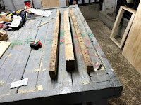
I had a number of four-foot-long pallet stringers that were made from walnut, which was a nice dense hardwood - meaning that is should have a decent amount of strength,
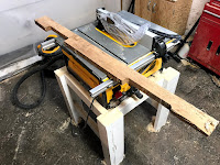
The first thing that I did was cut the stringers down to 2 X 2 boards and trimmed them to the specified length of 44 inches.
At the same time, I took a length of 4 X 4 that I had on hand and cut it down to a 2 X 3 board.
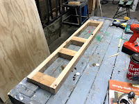
Next, I cut the 2 X 3 board into four 4 inch lengths to serve as ladder rails and I laid out the basic structure of the chassis on my workbench with a ladder rail on each end of the frame rail and the remaining two ladder rails where located in the center of the chassis with a 1-foot gap separating the 2 rails.
With everything in position, I then secure the ladder rails to the frame rails with 3-inch deck screws.
With the screws in place, the basic structure of the chassis was complete.
At that moment I took the opportunity to give the chassis a quick coat of black paint - I figured that it would be easier to do that now than later on where there was wheels attached and an engine sitting on top of it
Returning back to the drawings, I noticed that there was some additional reinforcement to the front of the chassis where the front axle of the tractor would be attached.
The drawings showed that the added reinforcement was accomplished by attaching two pieces of 8 inches long 2 X 3 above and below the front ladder frame of the chassis.
Both pieces, in turn, were attached to the chassis with 1/2 inch carriage bolts.
With that bit of information, I cut out two 8 inch blocks of 2 X 3 board.
Looking at the plans again, I noticed that the bottom block had a bit of a downward taper on both ends. The reason for this taper from what I could tell was to allow for travel of the front axle when going over uneven ground.
The plans didn't really specify what the angle of the tapers should be, so I made an assumption that the tapers were a 30-degree angle.
The other 2 marks, which will be used to attach the 2 blocks of wood to the chassis with carriage bolts.
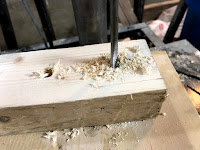
I then drilled a 1/2 inch wide hole at each mark.
Using the top block as a guide, I then drilled 3 holes into the front frame rail of the chassis and the bottom block
Finally, I threaded the top block through and secured everything in place with a 1/2 inch washer and nut.
I now have a complete chassis for the tractor. The next step is to make my chassis a rolling one with the addition of wheels. However, I will need to do make an expedition to find some cheap wheels.
So until I source some wheels, the chassis will have to sit on the workbench for now. My goal is to have a tractor up and running by the end of the summer - but time will tell.


No comments:
Post a Comment