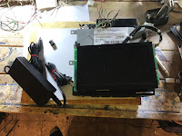
Over the past month or so, I've been playing with a DVD player that I had rescued from my local salvage yard with the idea of preparing it for a new life in my home.
While I can easily get the DVD player to start up and play movies, the DVD player was reliant on the vehicle's radio for sound, so the movies the DVD player showed were definitely of the silent variety.
While it would be fairly simply to hook up an audio amplifier to the audio outputs of the DVD player and connect a couple of wired speakers to the amplifier, I wanted to add a bit of a twist to this project and make the audio from the DVD player wireless.
The obvious choice would have been to hook the DVD player up to a Bluetooth based connection, but I really wanted to keep the cost of the project down to a minimum. With that criteria, I ended up settling for a much more older, but still a very robust technology - Infrared.
Before Bluetooth became the norm, the vast majority of wireless audio headphones used infrared as the means of transmitting audio signals. While they did work well, they did suffer from the drawback that the infrared transmitter and receiver needed to be in direct line of sight of each other in order to work, something that is not an issue with today's Bluetooth devices.
The good news though, is that transmitting infrared audio is fairly simple, requiring a relatively few parts to construct. A quick look on eBay turned up several infrared transmitter and receiver kits for only a few dollars. A quick click on the Buy Now button and I had 2 kits heading my way.
After a few weeks, the kits arrived.
Now one thing to note - that old saying "You get what you pay for" is still true. While I did get the kits in good shape and came with all the parts there was one thing that was missing - Instructions.
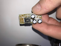
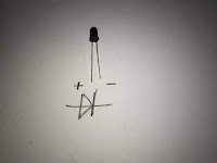
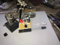
Now to the kit manufacture's credit, the printed circuit boards were very well marked.
Next I installed the socket for the amplifier chip (don't install the chip itself onto the board) .
Looking at the socket, there should be a small notch in one end of the socket itself - this notch should match a notch marked on the circuit board location for the socket. Make sure that the socket is seated into the board with the notch markings matching and solder the socket into place.
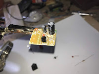
To finish up the board, I just soldered in the connectors for the speakers and the power, insert the amplifier chip into the socket (make sure that the notch on the chip aligns with the notch on the socket) and the receiver board is done.
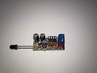
The assembling of the transmitter board is very similar, albeit with less parts. Assembly followed the exact same process that I followed for the receiver.
With the infrared transmitter and receiver all wired up, it's now time to try them out on the DVD player.
While waiting for the kits to arrive I had gone out and bought a 12 volt power supply and a power connector to hook up to the DVD player.
Luckily the Infrared transmitter also ran on 12 volts, so hooking it up to power was a simple matter of soldering it in with the power connection for the DVD player.
The audio input for the transmitter was a standard small head phone jack. For testing purposes I soldered the left side audio inputs of the DVD player to a similar sized headphone plug and plugged it into the headphone jack of the transmitter.
With everything all hooked up, it was time for a quick smoke test. Connecting the power to the DVD player, the red LED on the transmitter lit up with no smoke in sight - so far so good.
With the transmitter hooked up, I then hooked up the receiver. Hook up was a simple matter of connecting the receiver to a small speaker and powering it up with a 9 volt battery.
Finally all I had to do make sure that the infrared LED's on the transmitter and receiver were pointing to each other, I then put a DVD into the player and sat back and watched the show.
How did it turn out?
Not too bad. It transmitted the audio over a fair distance (about 10 feet) and the sound quality was pretty decent, despite the fact that I was was using an almost comically small speaker. Definitely promising enough to continue on with the project.
The next step is to now figure out how to enclose everything in a nice "home appropriate" enclosure - Stay tuned!









No comments:
Post a Comment