In my last post on the garden tractor restoration, I had just finished installing the new engine and gotten the fuel and throttle connections all done.
The only thing that I needed to do to get the engine going (and in theory, the tractor moving) was to hook up the electrical system.
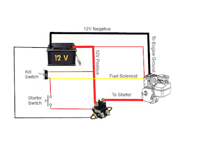
In principle, the electrical system for the tractor is fairly simple. The engine block is connected to the negative terminal of a 12 Volt battery.
In principle, the electrical system for the tractor is fairly simple. The engine block is connected to the negative terminal of a 12 Volt battery.
The fuel solenoid is connected to the positive terminal of the battery, which allows fuel to enter the carburetor.
The engine is then started by applying Positive 12 Volts to the terminal of the engine started, which should turn the engine over, and if everything is set up correctly the engine would start.
To shut the engine down, I would remove the power to the fuel solenoid, which of course would cut the fuel, shutting the engine down.
The issue with modern garden tractors is that they have a myriad of safety switches in place, that shut down the engine if certain operational situations exist (reversing with the PTO on or if there is no one in the driver's seat for example).
Since I will not be running the PTO with this tractor, I figured that I can just remove the safety switches and all the associated wiring and install something much simpler.
The plan is to make a wiring system that will comprise of a "kill" switch that would be connected to the positive terminal of the battery and will be used to turn the fuel solenoid on or off. Also connected to the kill switch will be a push button that will be connected to the ignition start switch post on the solenoid.
The idea is that the kill switch needs to be turned on before we can turn the engine over and start it.
At that same time, I removed the starter solenoid and gave it a quick test by hooking up the starter posts to a multimeter and connecting the ignition switch posts to the battery. I was greeted with a satisfying click from the solenoid and multimeter showing a connection between the posts - indicating that the solenoid was working fine.
Now that I had a clean slate to work with, I started assembling the electrical system by installing the
solenoid, which was done by bolting it to the side of the tractor engine bay with a couple of bolts.
Taking a looked at the engine, I noticed that there was a 2 wire connector coming out near where the magneto was located. Doing some research, I found out that this connector had one wire that acted as an alternator feed, which could be used to charge the battery. The other wire was a power feed for the tractor headlights.
Luckily I had a connector that fit, so I plugged it into the engine and connected the one wire back to the positive terminal of the battery so that the battery could be charged with I was driving around.
I also had a length of wire for the headlights, which I will connect up when I start to reassemble the tractor.
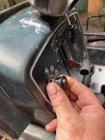
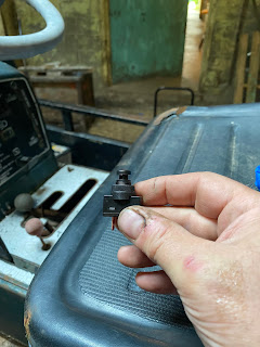
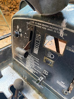
The next step was to install the kill switch. I purchased a round toggle switch from my local hardware that looked like it would be a good fit for the opening that the key for the tractor. That was done by just removing the old keyed switch and popping in the new toggle switch.
While I was at the hardware store, I also grabbed a push-button switch which I will use to start the engine.
While finding a spot to put the kill switch was pretty easy to figure out, finding a location for the starter switch was going to be a bit more of a challenge.
On the tractor dashboard, there was an Ammeter that was originally used to measure the charging voltage to the battery. However, in the case of my tractor, the meter was broken. The nice thing about it though was that if I removed the meter, I did have a nice opening in the dashboard for the switch.
The issue however was that the opening for the meter was a bit too large for the switch. To accommodate this, I needed to build a cover plate that would cover the opening in the dash with a hole drilled into the center of it for the switch. I built one pretty easily on my 3D printer, however, I could have just as easily made it out of think plywood.
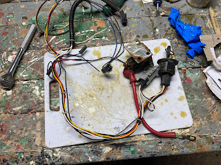
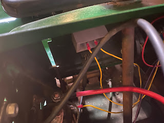
With the solenoid and switches installed, the final step was to do all the wiring connections as I had sketched out.
This was pretty easy since all the connections were the automotive spade-type connector, so I just needed to crimp connectors onto the end of the wires and plug them in.
Once things were wired up, it was time for a test.
This is a good sign! I now had a tractor that at least started and ran.
To see if it would actually move, I lifted the rear wheels up on top of some wooden blocks so that the wheels were off the ground and put the tractor in gear. I was quite relieved to see the wheels turning.
It looks like that the tractor was going to be viable mechanically.
Now to look into some of the more cosmetic details.






No comments:
Post a Comment