With the engine all squared away, I now could focus on the other parts of the tractor. One part that I had noticed when I was bidding on the tractor was that one of the rear tires was horribly cracked and in dire need of replacement.
I did some pricing on a new tire for this size of tractor, and I was absolutely floored at the price - basically, I was literally doubling the value of my tractor by installing a new tire. Well, I couldn't really use the tractor without it, so I held my nose and soon a new tire was on its way.
While I was waiting for the tire to arrive, I decided that I should at least prepare for it by removing the rear wheel from the tractor, remove the old tire and perhaps freshen up the rim with a fresh coat of paint,
Little did I know that I was in for the most frustrating part of the whole tractor rebuild.
On MTD tractors of this vintage, the rear wheels are attached to the rear axle by sliding the axle through the wheel rim and locking the axle to the rim with the use of a shaft key that fits into a slot cut into the rim and the axle. The whole thing is kept in place with a cotter key and a washer fitted to the end of the axle and fits snugly against the front of the wheel rim.
It's actually a very simple and effective way to attach a wheel to a drive axle and the theory is that to remove the wheel from the axle, all you need to do is remove the cotter key and the washer and the wheel just slides off the axle.
While that may have been true almost 40 years ago when the tractor was new, It certainly wasn't the case today, Decades of rust and dirt had pretty much welded the wheel to the axle. Which became very evident when I tried to remove the wheel by pulling on it after removing the cotter key.
Even some "gentle" persuasion with a rather large hammer didn't seem to budge it. After a lot of swearing and a smashed thumb, (thanks to the hammer) I needed to reconsider my strategy.
I first thought about using a large gear puller that I had on hand. with the idea of attaching the gear puller to the outer rim of the wheel and putting pressure on the front of the axle, thinking that it would put a lot more pulling force on the axle than I would have by just tugging on it.
While it seemed good in principle, I had to quickly stop when I started bending the outer rim of the wheel out of shape.
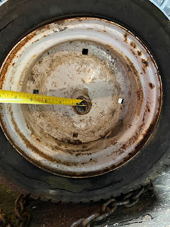
After another re-evaluation of the situation, I then noticed that there were a couple of 1/2 inch holes near the center of the rim, where the metal in the rim was a lot thicker.
Noticing this, I decided to build a very simple wheel puller that would take advantage of this.
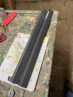
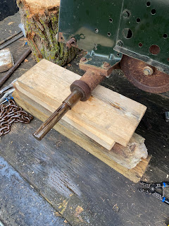
The first thing that I did was to put the angle iron together so that they formed a "C" where the middle part of the formed a 1/4 inch thick section of iron. I then clamped the 2 pieces of iron together with a couple of vice grips.
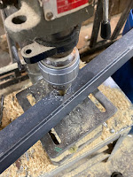
Next, I marked the center of the thickest part of the iron "C" and drilled a 3/4 inch hole through the iron with a stepped drill bit.
Next, I took the length of a 3/4 inch threaded rod and attached a nut and washer on one end of the rod and inserted the rod through the hole that I had just drilled.
With the center rod installed in the angle iron. The idea is that the rod will be positioned on top of the axle,
The next step was to figure out where to drill the holes in the angle iron for the rods that I will also be inserted through the holes in the wheel rim.
I did this by measuring the distance between the center of the axle to the center of one of the holes in the wheel.
Taking that measurement, I marked the distance on either side of the hole that I had drilled into the angle iron and drilled 1/2 inch holes at those locations.
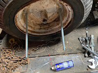
Next, I took two lengths of 1/2 inch threaded rod and attached a nut and a washer at one end of the rods.
I then fed the rods through 2 parallel holes in the wheel so that the nuts and washers are in the back of the wheel.
I then fed the 1/2 inch rods through the holes that I drilled into the angle iron and attached another set of nuts and washers at the end of the rods.
I tighten up the nuts on the 1/2 inch rods until the 3/4 inch rod was snugly centred on the axle.
From this point forward, I kept tightening the nuts on the 1/2 inch rods with a wrench that had a long handle, gradually applying more pushing pressure on the axle and more pulling pressure on the wheel itself.
Eventually, there was enough pressure being applied that the wheel finally broke free and slid off the axle.
That was a pretty painful experience, but at least I got the wheel off, and actually I came away with a new tool that I can use the next time I need to tackle a wheel on a lawn tractor









No comments:
Post a Comment