A few months back I published a series of posts around the construction of an electronic counter that would provide me with a constant display of the web traffic to this website.
The counter has been working away for a number of months now with no issues or complaints, well maybe one complaint,,,
While the counter does work beautifully, it is also just a lump of wires and electronic components that's been sitting on my desk in an unsightly mass. Additionally, the wires have recently become an attractive plaything for some of the furrier members of the household.
Obviously, if I wished to have my new toy to continue to function, I needed to do something.
In my last post, I did some experimenting with the Cricut Maker, a new tool that we recently got. One of the reasons that I was intrigued by the Maker was that it was capable of making very accurate cuts in thin sheets of plywood.
After some initial experiments with the Maker, I was ready to try my first project - a proper enclosure for my web counter.
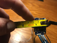
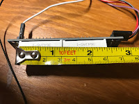
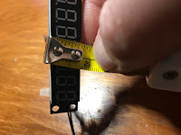
To start, I took some measurements of the LED display board, including making allowances for the wiring that would be connecting to the board and I also took measurements of the Wemos board that is used to drive the display and read the web counter data off of a wifi connection.
Based on the measurements that I took, I determined that a box that was at least 4 inches wide and 3 inches deep would do the trick.
Armed with my measurements I then looked for a way to design my box.
The Cricut Maker does come with a very powerful design tool (which actually looks very similar to the Easel tool that I use for my CNC router) but I didn't quite trust my artistic skills enough to want to use the tool to "hand roll" the parts for the enclosure.
The tool did have support for loading Scalable Vector Graphic (SVG) files. These files are typically used in a lot of Computer-Aided Manufacturing applications such as laser cutting.
Thinking that there may be some handy sources that would allow me to painlessly build a box, I went to the internet.
After a quick search, I came across MakerCase - a site that was geared to producing cut out patterns for any custom sized box that you would like.
While MakerCase is geared towards people using laser cutters, it did have the ability to download your creations to an SVG file.
I found the tool to be very easy to use, you simply enter the dimensions that you want the box to be, how many sides you wanted the box to have and whether you wanted the panels to have straught or fingered edges (fingered edges usually give you a tighter bond when you assemble the box).
The MakerCasse tool also gives you a 3D view of your finished box before you commit to cutting it out.
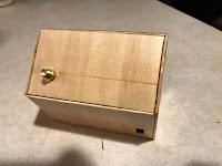
After some playing with various designed, I settled on enclosing the counter in an eight-sided enclosure, which resembled a little bit like a house.
Once I was happy with how it all looked, I downloaded it all to an SVG file.
Returning to the Cricut design tool I loaded up the SVG file and got things ready to create my first box
Since I still wasn't quite convinced that I had the size correct, and I still needed to determine the locations that I wanted the openings for the LED display and the USB power and wifi connections for the Wemos, I didn't really want to commit my design to plywood just yet.
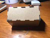
In order to serve as a work in progress prototype, I decided that my first enclosure should be made from something more expendable - cardboard that was once used as a cereal box,
So I loaded up the cardboard into the Maker and hit the Go button on the designer tool to start cutting out the pattern
Once the patterns were cut out, it was a pretty straightforward matter of assembling the box with some tape.
As a referral, I used the 3D rendering of my box on the MakerCase site as a guide
With the box assembled I then did some test fitting of the LED display and the Wemos board to determine the best location for the openings that I will need to cut into the case.
Once I had made that determination, I then took measurements of the LED display part of the display board and likewise did the same for the USB and wifi connections for the Wemos
Returning to the Maker design tool, I then marked the areas that I need to cut out on my box pattern.
I took extra care in making sure that the size of the areas that I wanted to cut out was as accurate as possible.
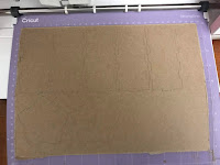
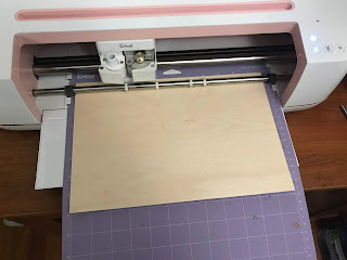
Once I was satisfied with where I wanted the openings to be cut, I then loaded in a sheet of 1/32 inch plywood and sent the command for the Maker to do its thing,
After the cutting process, I was provided with a collection of wood box parts that were ready for assembly.
The assembly of the enclosure was pretty straightforward since I simply just repeated the assembly that I did for the prototype.
To assemble the enclosure I ran a thin line of glue along the edges of the panels and held everything in place with painter's tape until the glue dried.
I also made sure to leave one panel off the enclosure - otherwise, it would be fairly hard to install the electronics if the box was fully enclosed.
When the glue had dried, the last step is to install the electronics.
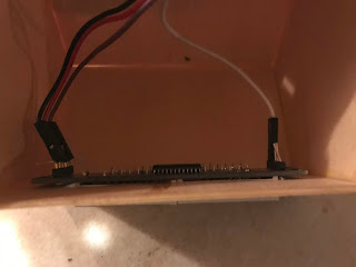
The first thing that I installed was the LED display board.
Installation was a simple matter of sliding the LED display through the opening in the enclosure and securing the board to the box with some hot glue.
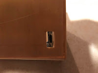
Next the Wemos board was installed inside the case, making sure to have the USB power port for the board line up to the open that I had cut into the enclosure.
When doing the install, I noticed that I had made the opening in the case a little too far away from side of the case that I was planning on installing the Wemos, To solve that issue, I hot glued a small bottle cap to the Wemos and then I attached to the whole assembly to the side of the case, again making sure that the opening and the USB power port lined up.
Next, I installed the wifi connector to the case and I then installed the last panel to the enclosure and secured it in place with glue.
As final step, I installed the wifi antenna, plugged in the USB power cable and the web counter was up and running
The web counter is now sitting on my desk safely cocooned in its attractive new home. For a first project with the Cricut Maker, I was quite pleased with how easy it was to set up and produce wooden parts that had such a high level of precision.
It's certainly given me to explore more projects with this Maker.















No comments:
Post a Comment