A few weeks back, my attempt to connect the rear wheels of my tractor to the engine ended in a complete failure.
Going back to the drawing board I decided that trying to do a 90-degree twist in the drive belt was just not going to cut it.
Unfortunately, this meant that I had to go with the more traditional route and have the engine drive to be more in line with the wheels, and avoid that 90-degree twist altogether.
The issue I had was that I still wanted to avoid having any moving belts as close to my limbs as possible.
After some thought, I figured that if I maintained my original plan to have the rear wheels driven by a belt that was routed down the center of a chassis, but make the connection to the engine as close to the front of the tractor as possible, that should make things reasonably safe.
Another issue that I now had was that my lawnmower engine would no longer work since I now needed an engine that had a horizontal drive instead of the vertical drive of the engine I had now.
Luckily, I did have another engine on hand from an old snowblower that hade that configuration, with the added bonus of also having an electric starter.
I removed the old engine and did a test fit of the new engine. Immediately I saw that the engine was quite a bit bigger than the original one, meaning that the engine enclosure that I had made was way too small. As a result, I had to remove more than just the old engine to make the new one fit.
After I stripped out the old engine mount, I focussed on creating the mounting brackets that I would use to attach the driveshaft with which I will connect 2 pulleys to it. The first pulley will be mounted outside of the chassis and be connected to the drive pulley on the engine. The second pulley will be mounted on the driveshaft inside the chassis and will be used to supply the power to the rear wheels.
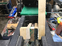
To create the mount, I selected a couple of 2X4 pieces that were about 4 inches long which will be used to hold the driveshaft and a piece of 1X4 that was to the length of the gap in the chassis to act as additional reinforcement for the driveshaft mount.
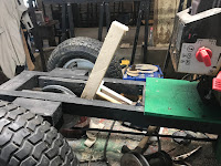
To install the mount, I first located where on the chassis the drive pulley of the engine would be aligned to and I secured the mount reinforcement along the top of the chassis at that location and held it in place with screws.
I then installed the 2X4 mounts to each side of the chassis, placing them underneath the reinforcement block and secured them to the chassis and the reinforcement block with screws,
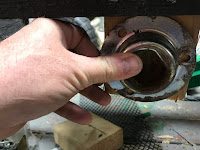
With the mounts installed I then did a test fit of the bearing mounts over the wooden mounts and I marked the location on the wooden mount to drill a 3/4 inch hole through the mount for the driveshaft.
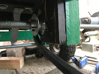
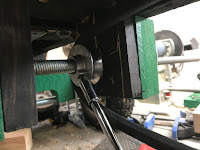
With the holes drilled, I then mounted the engine on top of the chassis and did a test of the driveshaft and the outside pulley to confirm the pulley alignment and confirm that the belt between the two pullies is as straight as possible.
At the same time, I also did a test fit of the pulley inside the chassis to make sure there was enough clearance to run the belt to the rear wheels.
Once I was satisfied with the alignment, I secured the pullies in place and installed the belts.
For the belt that drove the rear wheels, I deliberately made the belt a little loose. The idea here is to make the belt act as a simple transmission by making a tensioning device where if there is no tension, the belt just lies loose on the pulleys, not moving the tractor, but with the addition of tension, the belt tightens up on the pulleys, driving the tractor forward.
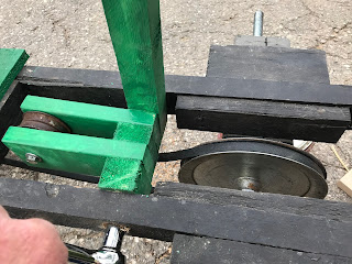
I figured that the easiest way to build the "transmission" was to attach an idler pulley to a lever that would be bolted to the chassis. The idea would that whenever I pushed on the lever, the idler pulley would push down on the belt, creating tension, moving the tractor forward.
Luckily I had an idler pulley that I had salvaged from the snowblower that would work.
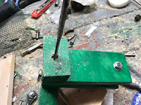
To build the "transmission" I took a couple of 5 inch long pieces of wood and drilled a 3/8 inch hole at one end of them. I then took a 3/8 inch bolt and I assembled the 2 pieces of wood together, sandwiched with the pulley and some washers, by feeding the bolt through the hole that I had just drilled.
I then tightened everything together with a nut.
I then took the assembly and did a test fit so that the idler pulley was centered on the drive belt.
From there I took measurements on the gap between the assembly and the chassis and I also marked on the chassis where the best position would be for the assembly to be attached to the chassis.
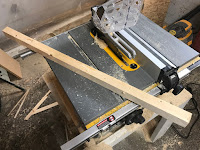
Taking a length of 2X2, I then cut out a 16-inch length to act as a lever to engage the idler pulley and cut out 2 smaller pieces and trimmed them to size to fit the gap between the pulley assembly and the chassis.
I then attached the lever and spacers to the end of the idler pulley assembly and gave it a quick test fit to make sure it was relatively snug between the chassis rails and that the pulley was positioned properly over the pulley.
Next, I drilled a 3/8 inch hole through the assembly where the lever was located and likewise drilled holes into the chassis where I had marked earlier for mounting the transmission assembly
Finally, I put the transmission assembly in the chassis and fed a 3/8 carriage bolt through the hole that I had drilled into the chassis and assembly, tightening things down with a nut.
With that, it was time to try it out.
Initially, things were working well, as I pushed forward on the lever, the drive belt tightened and the tractor moved under its own power, occasionally trying to run away from me.
While it worked well moving its own weight, it started having troubles when I tried to move while I was sitting on it. Unfortunately, that was a bit too much and I was finding that the belt started to severely slip and smoke.
So, some more tuning is needed but we are headed in the right direction - back into the shop it goes.









No comments:
Post a Comment