A few weeks back I embarked on building a small garden tractor based on plans that I had found in a copy of Mechanix Illustrated from 1941. The unique thing about this tractor was that it was built completely out of wood.
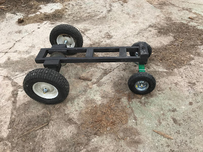
I managed to put together the chassis for the tractor, so the next step would be to attempt to put some wheels on to create a rolling chassis.
The front axle will also look after the steering for the tractor, so while the front wheels would need to turn freely, I also needed to make sure that the whole axle assembly itself pivoted on the tractor's chassis.
Looking at the original plans for the tractor, the front axle assembly was cut from a piece of 2X3 wood at a length of 16 inches. The original plans also had the front axle assembly cut out to have fairly elegant curves with a deep curved cut in the center bottom of the assembly to allow for a bolt to come through the center of the axle and attach to the chassis.
I did attempt to emulate this design for my axle, however, I found that the curved cuts greatly weakened the assembly, causing it to break when I tried to attach the axle rod and wheels.
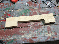
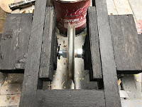
To get the greatest amount of strength for the front axle, I decided to simplify the design of the assembly by creating it as more of a U shape. I also created the assembly out of 2 pieces of hardwood which were joined together with glue and wood screws, ensuring that the assembly was as strong as possible
I then cut a 3/4 inch groove into the bottom of the axle assembly to accommodate the axle rod and I drilled a 1/2 inch hole in the center of the assembly to allow for bolting the assembly to the chassis
I then gave the assembly the appropriate paint job.
The next step was to completely assemble the front axle.
I first gathered the necessary hardware which included:
- Two 4 inch wheels - I got a could wheels that included pneumatic tires.
- A 2-foot length of 3/4 inch threaded rod,
- Some 3/4 inch nuts, and washers,
- A 6.5 inch long 1/2 diameter carriage bolt with nuts and washers,
- Two 2 inches wide and 4 inches long U bolts
- A 2-foot length of 1-inch wide metal strip
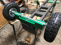
To assemble the front axle, I connected the front axle assembly to the chassis with the carriage bolt, making sure that I had a washer between the chassis and the axle assembly.
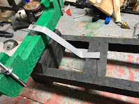
Next, I took the metal strip and drilled a 1/2 inch hole at one end of it. After putting a slight bend in the strip near the hole that I drilled, I then made a mark on the strip where it was making contact with the nearest cross member of the chassis.
I then cut the strip at the spot that I had marked and drilled a 1/8 inch hole at that end.
I secured the strip to the cross member with a 1-inch wood screw.
The metal strip will provide the front axle with additional support as we drive the tractor over any rough terrain.
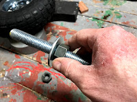
With the axle assembly attached I then threaded a washer and a 3/4 inch nut onto each end of the 3/4 inch threaded rod.
Next, I seated the rod into the groove that I had cut into the axle assembly and did a rough install of the wheels onto the axle rod, making the necessary adjustments so that the rod as even as possible in the axle assembly.
With the axle rod centered I then installed the U bolts onto the outside ends of the axle assembly, tightening down the U bolts until the axle rod was snug in the groove.
Finally, I installed 3/4 inch nuts on the ends of the wheels, fully securing the wheels to the axle.
With that, the front axle and wheels were now attached to the chassis
Moving my way back on the chassis, I started work on the rear wheels.
I first needed to source some appropriate rear wheels for the tractor. I could have simply bought a couple more 4 inch wheels, but that would make my tractor more of a go-cart than an actual tractor. I really needed to get some large wheels.
Luckily a pair of 16-inch wheels from a defunct lawn tractor came up for sale nearby.
Looking at the plans, the tractor rear wheels were driven by a pulley that was directly attached to the rear wheels themselves, which meant that the drive belts were in real close proximity to where my legs were going to be located. I didn't think that would be a safe situation.
I decided that I would abandon what was outlined in the plans and take another approach.
My plan is to have the pulley centered on the rear axle, positioning the drive train for the tractor to be contained within the chassis - out of the way of the driver's body parts.
To do this, I decided to mount the rear wheels to the chassis with a couple of 4 X 4 post sections, which would encase the rear axle rod.
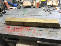
To start the process I first gathered up a 4-foot length of 4 X 4 and I sourced a pulley from a junked snowblower.
To determine the location for the rear axle, I first did a test fit of the pulley inside of the chassis. I placed the pulley such that is was a close as possible to the back cross member of the chassis but still left an adequate amount of room for the pulley to turn freely.
Once I had the location sorted out, I made a mark on the chassis that corresponded to the center of the pulley.
Next, I took the 4 X 4 post and cut it into two 2 foot sections.
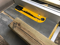
Next, I took the posts and cut them lengthwise so that I had a 3 X 4 and 1 X 4 piece.
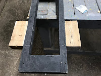
Taking the 3 X 4 wood pieces I then cut a 1 inch X 1-inch groove in the middle of the wood
The two 4 X 4 posts will serve as the attachment point for the rear axle to the tractor's frame.
Since there will be a fair amount of stress being put on the rear axle when the tractor is in motion, I need to make sure that the axile is as beefed-up as possible.
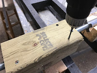
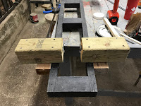
To do this, I reinforced the back of the chassis by screwing in a pair of 2 X 4 wood blocks along with the outside chassis at the location where I will be mounting the back axile.
I then screwed the 3 X 4 portion of the axle housing to the bottom of the chassis, making sure that the grooves were aligned in a straight line, leaving a 4-inch gap in the middle of the chassis to allow for the installation of the pulley later on.
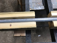
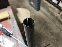
Next, I got a length of 1-inch metal conduit and did a test fit in the grooves of the rear axle mount.
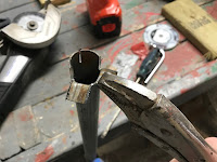
Using a pair of pliers, I bent the slots back so that they were perpendicular to the conduit.
The conduit was then installed into the back axle mount. The bent metal slots will act as a bushing, preventing the conduit from sliding out of the axle mount when the wheels are turning.
With the conduit installed, the axle mount was then sealed up by reattaching the 1 X 4 piece of the 4 X 4 and securing it in place with deck screws.
The final step in the process was to attach the rear wheels to the chassis.
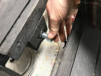
I started the installation by threading the rod through one of the metal conduits on the back axle mount. Once the rod started poking through the inside of the chassis I threaded on a 3/4 inch nut to the rod on the inside of the chassis.
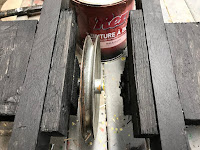
I continued to work the rod through some more, while still threading the nut further on the rod. Once I had enough rod exposed on the inside of the chassis, I then inserted the pulley onto the rod.
Continuing to push the rod through the conduit, I then threaded on another 3/4 inch nut onto the rod such that I had a nut on each side of the pulley.
My plan is to fasten the pulley onto the rod by tightening the 2 nuts against the pulley as tightly as possible. While the traditional method is to cut a groove in the rode and insert a metal key between the pulley and the rod, I wanted to try this approach. I may still need to add a key at a later date, but I was curious to see if this worked.
Once I threaded the rod through to the other side of the axle mount, I centered the rod so that it had an equal length on each side of the chassis.
I then threaded on a 3/4 nut and washer on each end of the rod.
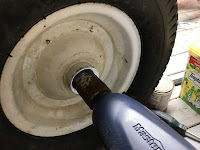
Next, I mounted the tires onto the ends of the rods and threaded another washer and nut.
I then tightened the wheels to the axles with an impact wrench.
Finally, I centered the pulley in the middle of the chassis and I tightened the nuts between the pulley as tightly as possible.
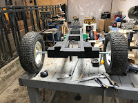
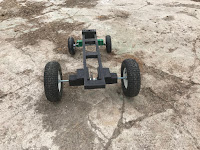
With that, the chassis now had wheels and the first piece of the drive train installed.
Taking the tractor off the bench, I gave it a few test rolls to make sure things assembled properly.
Now that the tractor can roll, the next step will be to figure out how to power this thing.
























No comments:
Post a Comment