A little while back I posted about my exploration in tracking gliders that were soaring around my area with a software-defined radio and some open-sourced software.
As I had mentioned, it all started with a mysterious phone last summer. Later that fall, I got yet another call from my new glider friend, wondering, since the gliding season was over for the year, would I be interested in tracking high altitude balloons instead.
It turns out that there is a bit of an enthusiast community out there that track and if possible, recover high-altitude balloon payloads. A good majority of these balloons are the good old weather balloon that is still very much in use in our high tech world today since they can easily ride along the jetstream, but the military also use balloons in preparation for artillery exercises and there is also an active amateur radio community that use balloons to transmit radio traffic.
The central repository of all high altitude balloon knowledge can be found at habhub.org. The site includes information on how to set up a tracking station using a software-defined radio dongle - similar to the one I used for tracking gliders.
Setting up a receiving station is fairly well documented at the site, so I won't really focus on how to do that since I will leave that to the experts at Habhub to explain. But I did find details a little skimpy on what sort of antenna to use.
Most balloons use frequencies in the 402 to 405 MHz range and transmit at a power of around 50 to 100 milli-watts. Even though they are transmitting at a very low level of power, since balloons can reach 10's thousands of feet in the air, they do have the potential to be received from great distances.
I first tried using an old discone antenna that I had from when I listened to a scanner radio. The discone had a wide frequency range and wasn't particularly tuned for the frequency that the balloons used, but I did manage to pick up short snippets of balloon transmissions over the course of a few weeks.
Based on the information I was getting from Hubhub, I should have been getting a few hours' worth of transmission data, not a few seconds, so basically I needed to rethink my approach.
In chatting with my glider mentor, it was strongly suggested that I consider using a yagi antenna and retire the discone back into the corner of the shed that I had pulled it from.
Yagi antennas do a very good job of picking up and amplifying weaker signals into a receiver, so it would make sense that this would be a good choice for picking up flea powered weather balloons.
The main issue with yagis is that they are highly directional - meaning that they need to be pointed at the radio that is transmitting - if you don't point in the right direction, you won't hear anything.
Luckily for me, the majority of the weather balloons in my area are launched north - northeast of my location, so in theory, if I point a yagi in that direction, I should have better luck hearing something.
While yagi antennas are a very common item for an amateur radio operator to have and there are a lot of yagi antennas that have been manufactured for the ham radio market, there just isn't the market for yagi's tuned for weather balloons. I'll have to roll my own antenna.
Luckily I was pointed to a website hosted by Stephane Grandgirard. While my French isn't very good, the design Stephane has come up with looked to be very easy to build and the diagrams that were provided were very easy to follow.
Using his site as a guide, I went about building my own yagi antenna.
Stephane's design was built for portability with the idea that you can use the antenna in a mobile operation to track down and recover landed balloons. As a result, his antenna was built to be as light as possible, which also made it fairly fragile. My antenna is meant for a more permanent outdoor installation, meaning the overall portability wasn't really a factor, but being as robust as possible certainly was.
With those criteria in mind, I marched on down to the hardware store.
Upon my return to the shop, I had a 3-foot length of 1.5-inch hardwood dowel and three 3 foot lengths of 1/4 inch round aluminum rods.
To make the antenna, I first needed to mark and drill the holes into the dowel in order to install the aluminum rods, which will serve as the radiating elements for the antenna. Yagis' usually have a number of radiating elements (or rods), in particular, yagis usually have an element that acts as a radiator, an element that acts are the driven element (which is where the radio directly connects to the antenna), and a number of elements that act as director elements.
To start, I used Stephane's diagram as a guide and marked the location of the third director element at one end of the dowel. Once I marked that location I then measured down 56.4cm on the dowel and made a mark at that spot for the antenna's radiator element.
From the spot I marked for the radiator I then measure up the dowel (in the direction of the spot that I marked for the third director) 13.7 cm and I made a mark that spot for the driven element.
Next, I measured down another 10.6 cm from the spot I made for the driven element and made a mark for the first director element. Finally, I measured down another 13.8 cm and made a mark for the 2nd drive element.
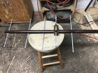
At the end of the day, I am looking to construct an antenna that will look something like this:
When I marked the locations for the antennas elements, I made sure that the marked spots are located in a straight line along the length of the dowel in order to make are the elements are as parallel as possible when they are installed.
Once the locations were marked, I then sandwiched the dowel between 2 square strips of wood, secured in place with a clamp. I did this in order to maintain that straight line on the dowel when I drilled the holes.
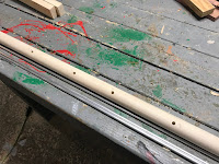
Next, I installed a 1/4 inch drill bit in my drill press and drilled a hole through the dowel at each place that I had marked.
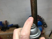
Once completed, the dowel now had a series of holes through it. Since the antenna is destined to live outside, I took the opportunity at this point to give the dowel a couple of coats of paint.
I next turned my attention to the 1/4 inch aluminum rods. I measured out and cut the rods into the following lengths:.
- 36.7 cm for the Radiator element
- 33.2 cm for the First Director element
- 30.9 cm for the Second Director element
- 29.2 cm for the Third Director element
This still left me with one 3 foot length of aluminum rod left over which I used to construct the Driver element for the antenna
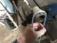
To construct the driver element I needed to create an element that was 32.6 cm long, with a 4 cm semi-circle on each end with another side of the element meeting in the middle. In essence, I need to have the element looking something like a flat oval.
To construct the element I first needed to have the 32.6 cm length of the element marked out in the center of the rod. I did this by subtracting 32.6 from 91.44 (91.44 cm = 3 feet) which gave me 58.84 cm. I divided that number by 2, which gave me 29.42. I measure in 29.42 cm from each end of the rod and made a mark at that location.
Next, I used a 1.75-inch diameter round object (I used a large socket) and I bent the rod around the circle on one end so that I had a semi-circle with the mark that I made on the rod was on the top end of the semi-circle.
I then inserted the driver element into its corresponding hole in the dowel by inserting the long part of the element through the hole.
Next, I bent the other end of the rod into a semi-circle that the spot that I marked at the other end of the rod until I got what was basically looked like a paper clip around the dowel
Refocussing my attention back on the driver element, I attached 2 large spade lug onto the two ends of the element by simply crimping them onto the rod and I further protected the connection from the elements with some electrical tape.
In order to help keep the driver element in place, I needed to have some sort of support in place for it. I took a piece of 2-inch thick scrap wood and I drilled a 1.5-inch hole in the wood scrap.
I then ran the piece of wood through my table such that I cut through the middle of the hole I just drilled.
I then further cut the piece of wood until I have a 4 inch long, 1-inch high piece of wood which a 1.5-inch semi-circle in the middle of it. I tested the fit by placing it on top of the dowel and underneath the 2 ends of the driver element. The element ends should sit fairly snugly on top of the wood piece
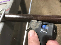
Once I was fairly happy with the fit, I then glued the wood piece in place on top of the dowel
To finish the build, I then installed 1/2 inch nuts, bolts, and washers into the lugs on the end of the driver element. These will act as the connection points for the coax cable when I go to install the antenna.
That last step effectively completes the construction of the antenna.
To install the antenna, I connected the center wire and the shielding of my co-ax cable to the 2 bolts on the antenna and mounted the antenna on top of my shed (any location that had a clear line of sight of the sky would work).
A few days later a weather balloon was launched about 200km away from my home - and my antenna immediately picked it up.
So I'm now in the business of tracking balloons. The next goal is to try and recover one of those balloons if they happen to land fairly close to me. If they do, I will know!









No comments:
Post a Comment