The last time I worked on the tractor, I had mounted the engine to the tractor. Now I was faced with the prospect of attaching the engine to the rear wheels so that the tractor could actually move under its own power.
As I mentioned at the start of the build, I wanted to keep all the moving parts of the tractor's drive train as far away from my limbs as possible, My idea was to use the vertical drive of the lawnmower engine to connect it to the rear wheels with a drive belt that would have a 90-degree twist to a secondary set of pulleys that in turn would be connected to the rear wheels.
I got the idea for this arrangement from a set of plans for a wooden go-kart that has its wheels powered via that type of arrangement.
I'm not entirely sure how successful I will with this since I am not entirely sure how the belt will stay on the pulleys with that severe of a twist, but I am willing to give it a try.
To start the build, I first gathered up the various parts that I needed to make the drivetrain.
This included 2 pulleys (one to connect to the engine drive belt and the other to connect to the drive belt for the rear wheels). The pulleys were of different sizes in order to adjust the overall speed of the tractor. The pulleys also had a 5/8 inch opening in the middle to accept a shaft of that size.
Obviously, I also got a length of 5/8 inch threaded rod.
I also gathered two bearings with a 5/8 inch inner shaft diameter and a couple of mounts for the bearings.
I also gathered up a handful of nuts, bolts, and washers.
The only thing that I did not have on hand was a pulley to attach to the drive shaft of the lawnmower engine.
While I could have simply gone out and bought a pulley to fit the driveshaft, I did have the adaptor from the lawnmower that was used to connect the mower blades to the engine. The adaptor did have a couple of mounting points on it that I could use to mount something to the engine.
When I looked at the original plans for the tractor, I did notice that they did utilize what appeared to be wooden pulleys as part of the drive train for the tractor, so I was actually pretty curious about the feasibility of using wood for that sort of function. Since the blade adaptor looked like a really nice mounting point, I figured that I would make the engine pulley out of wood and attach it to the blade adaptor.
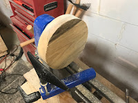
To make the engine pulley, I took a 2-inch thick piece of pine and cut it into a 7" X 7" square, trimmed off of the corners of it, and mounted it on my lathe.
Using a bowl gouge I then turned the block into a circle with a diameter of about 6 inches.
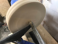
Next, I cut a half-inch deep groove on the edge of the circle to allow for a place for the belt to sit on the pulley
Finally, I smoothed one side of the pulley in order to remove any "wobble" potential when the pulley was spinning, and I marked the center of the pulley with the gouge.
In order to attach the pulley to the engine, I needed to have access to the center bolt that attaches the blade adaptor to the engine's driveshaft. To attach the adaptor I would also need to use a socket wrench to tighten the bolt.
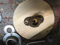
To accommodate this and to allow access for a socket wrench, I drilled a 3/4 inch hole through the center of the pulley at the mark that I had carved with my gouge.
To attach the pulley to the blade adaptor, I inserted the bolt used to attach the adaptor to the drive shaft into the adaptor and I center the adaptor on top of the pulley, using the bolt to center the adaptor.
Using an awl I then marked the location of the mounting holes for the adaptor on the pulley and drilled 1/4 inch holes into the pulley at those locations.
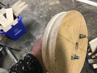
Using a couple of 3-inch long 1/4 inch bolts I then attached the blade adaptor to the pulley
After that, I attached the whole assembly to the engine's driveshaft.
With the engine pulley installed, I switched my attention over to the intermediate pulley section that will serve as a gear reduction section between the engine and the rear wheels.
I inserted the 2 pulleys onto the 5/8 threaded rod and did a test fit for the position on where I wanted to locate the pulleys on the tractor.
I wanted to make sure that the belt for the rear wheels had a little bit of slack since I wanted to use that section of the drive train to start and stop the tractor with the use of an idler pulley which would be used to increase and decrease the belt tension.
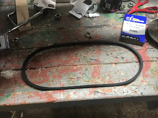
Once I determined the location I then measured the distance between the engine pulley and the pulley I intended to use for the gear reduction and grabbed a belt that size from the local hardware store.
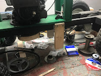
Next, I installed wooden hanger brackets at the location that I wanted to install the pulleys and drilled a 5/8 hole into the brackets to install the threaded rod (I positioned the pulley where I wanted to to be and used a pencil to mark the location for the hole).
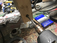
I then drilled a 5/8 hole into hanger brackets and gave the brackets some additional reinforcement
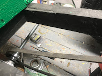
I then installed the pulley and rod into the hanger brackets and attached the belt to both pulleys, as outlined in the instructions that I got from the go-kart plans that I had
Giving the engine a couple of spins, unfortunately, confirmed my worst fears. The belt just simply could not stay on the pulleys.
While there was more than plenty of tension on the belt, it would not remain one more than a couple of turns of the engine.
I tried a few different approaches to try and solve for this issue, including making the pulley on the engine a lot smaller in order to make the belt as close in line as possible between the top and bottom of the pulley in the rod.
When that failed, I tried to create a guide around the engine pulley to also try and keep the belt as centered as possible, however, I kept finding that the belt still had a tendency to pop off the pulley.
At this point, I had to admit defeat on this approach and come up with a new plan.
So while this wasn't a success, I did actually learn some things in the process, and I was actually pretty impressed on the potential of having a belt pulley made from wood.
But I now need to plot what the next course of action I should take, but based on what I have learned I do have some ideas on what to do next.
Back to the drawing board. 😀













No comments:
Post a Comment